Building a C64 Saver Kit
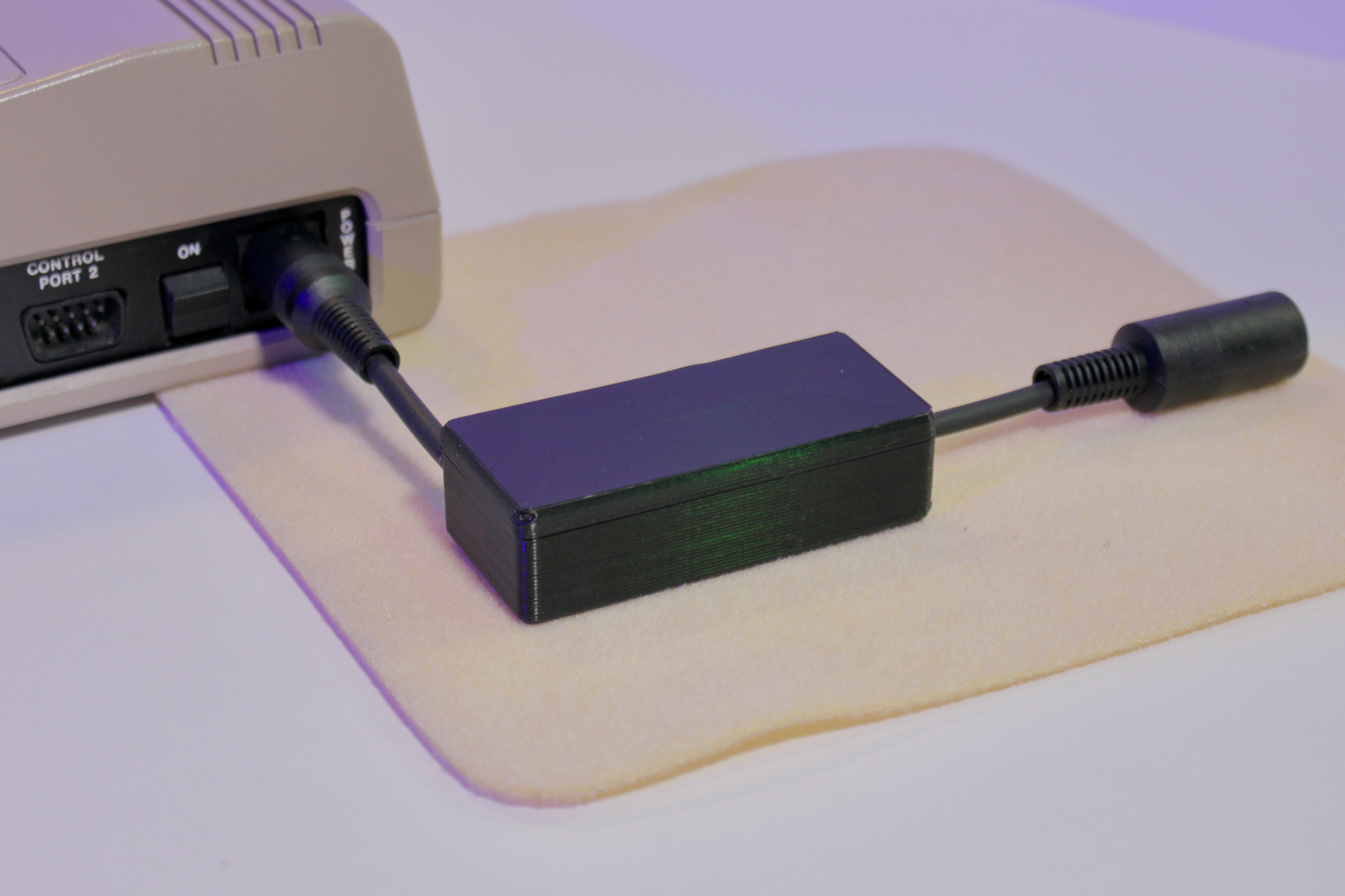
The C64 Saver is a device that is placed in between the power supply and the computer on a Commodore 64 or VIC-20. With the age of the power supplies, they can fail in a way that the DC voltage, normally 5 volts, can go over 5.5V and destroy the unprotected chips in the computer.
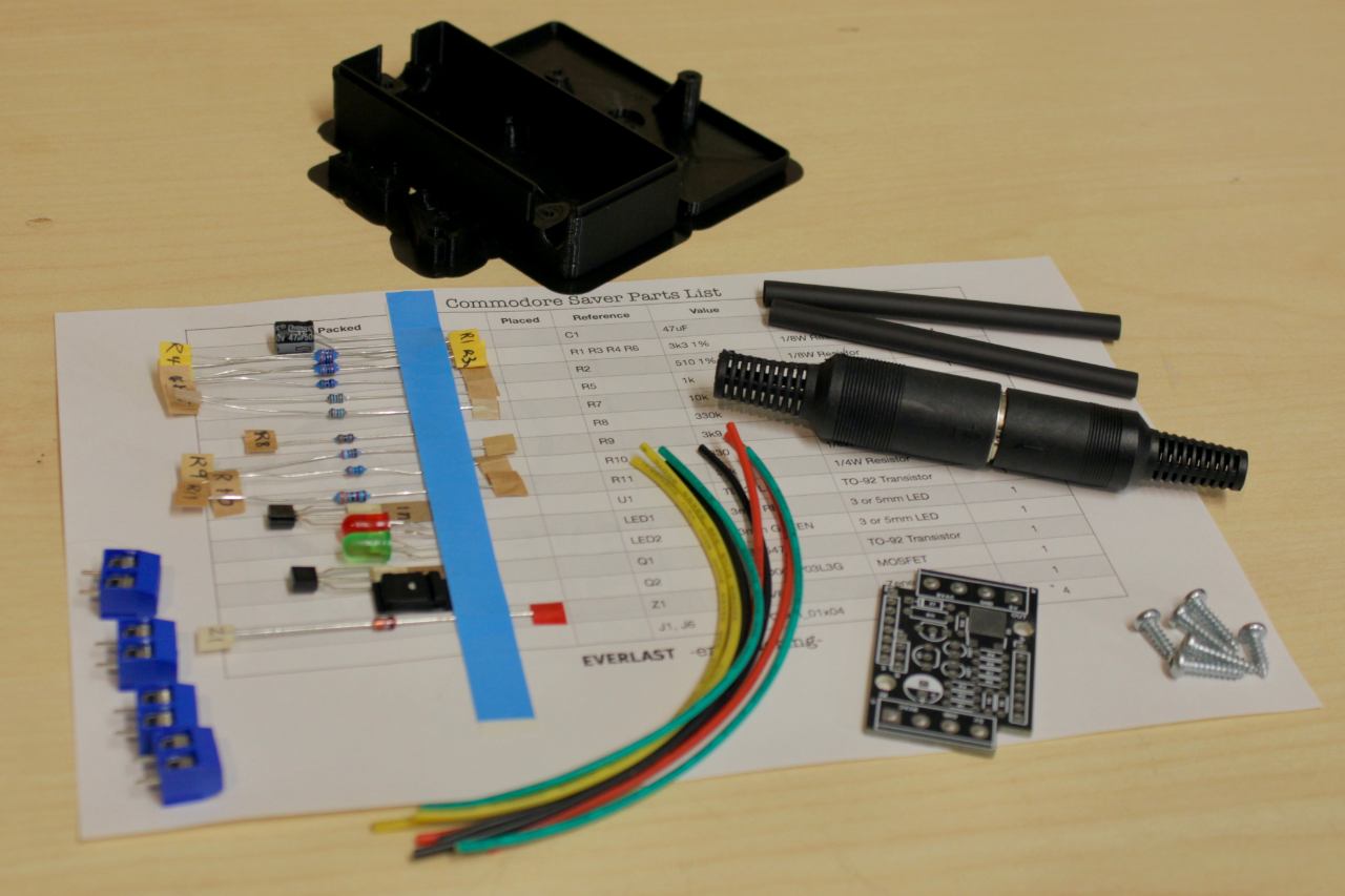
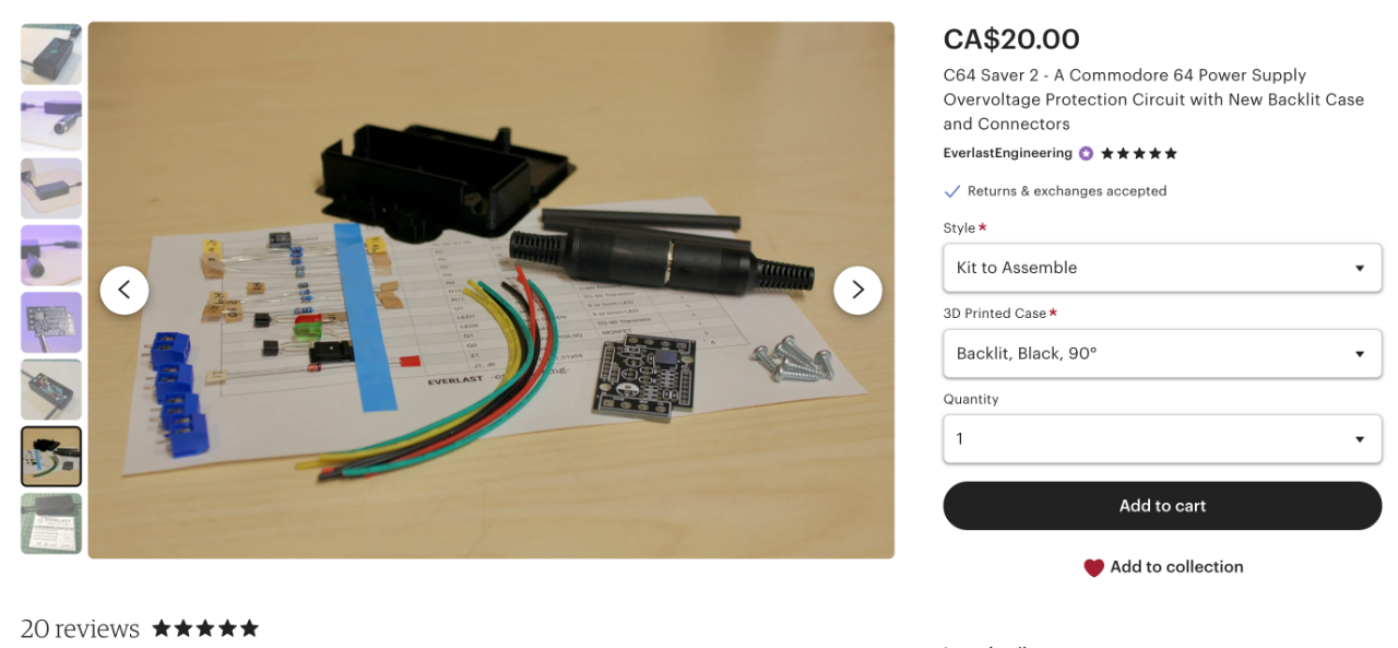
This is a walkthrough on how to assemble this from a kit, in particular, for those who have purchased the kit from my store available here. It's also available fully assembled.
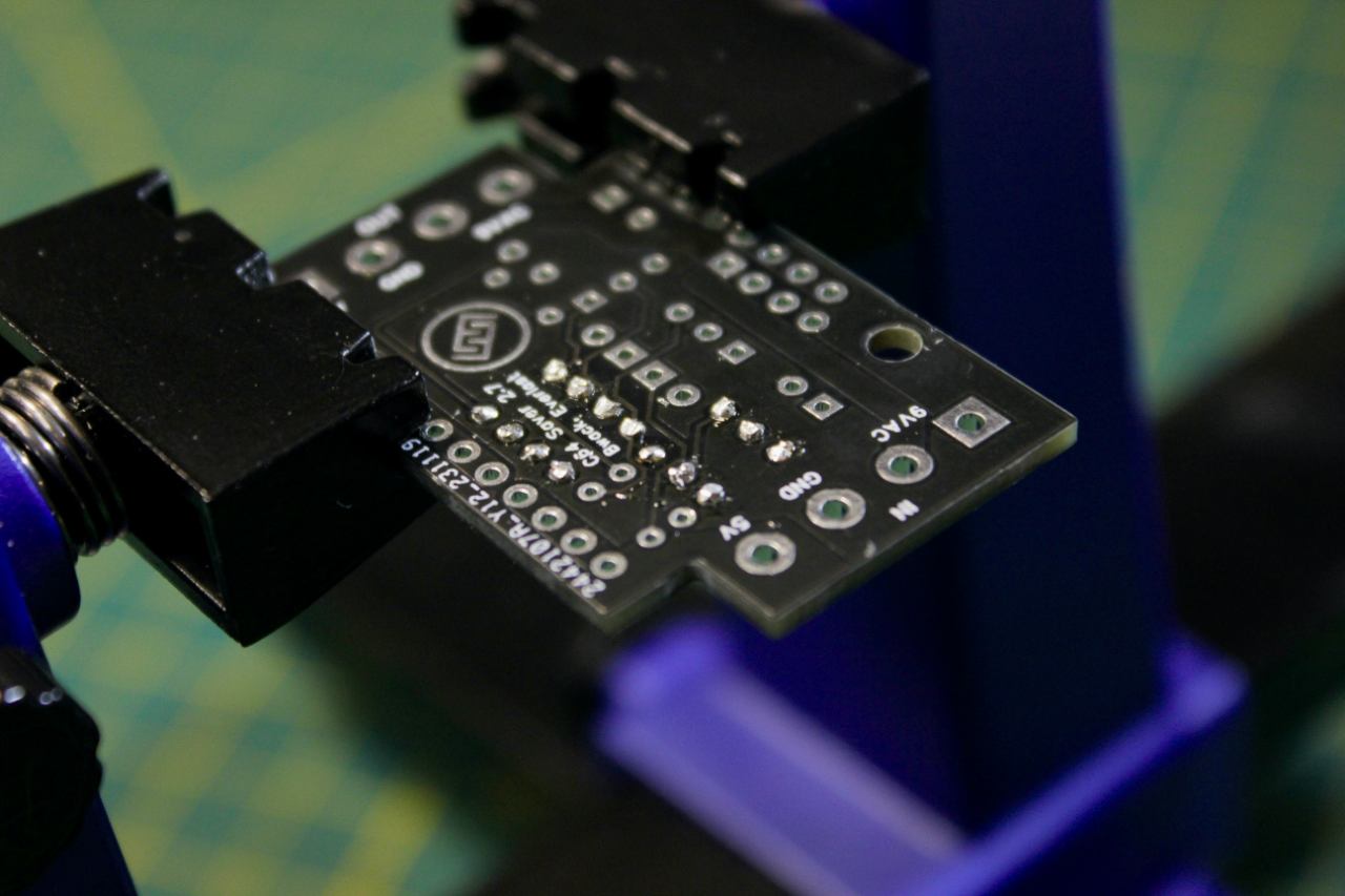
I suggest that you also open up a link to the Interactive Reference for help with identifying the proper location for components.
This is a great design by bwack, so many thanks to him for providing this as open-source. I've tested the response of this design and when the voltage crosses the shut-down threshold, normally around 5.4V, the output voltage instantly drops to 0. There is no spike, nor any delay. I'll be making a video demonstrating this shortly.
Let's Assemble!
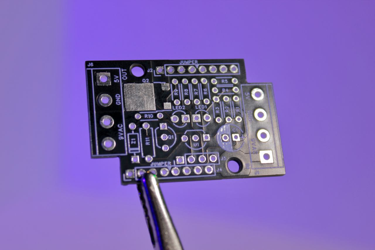
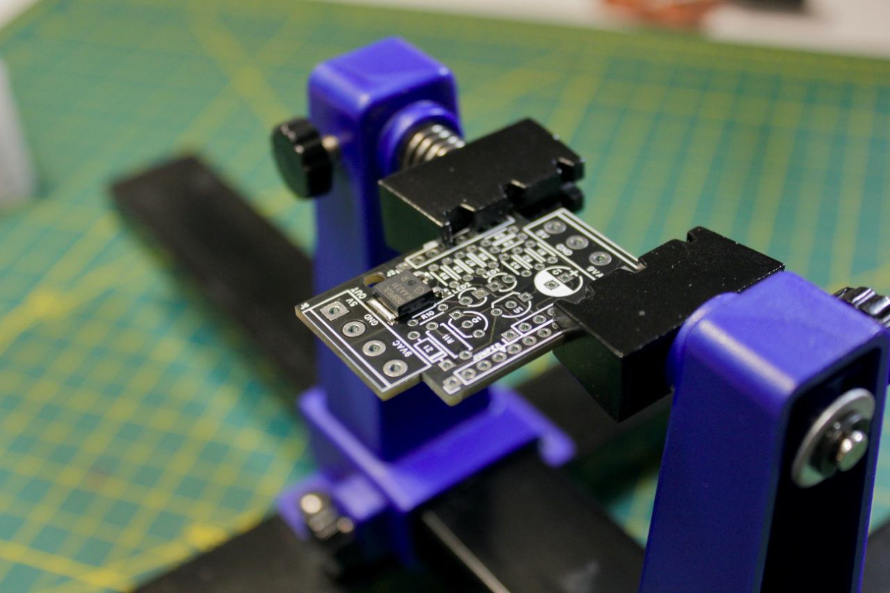
Find a nice way to hold the board, and let's install Q2, the MOSFET, first. I use lots of flux, tack down the chip by its little feet, then heat the edge of the sink at the top and wait for solder to wick down using high heat.
Use lots of flux! What's in the solder isn't enough. You must have more!
Melt some solder on a clean tip. Anchor the piece in place by soldering one point first, then inspect your placement. You can adjust it's position by melting that one joint easily, but not if you've already soldered two or more.
On the large output side of the MOSFET, I put the iron nearly flat across the metal to empart as much heat as I can out of the iron, and use ample flux and solder. The liquid solder on the iron transfers the heat very quickly to the FET before it gets wicked away.
Soldered in. Clean up all that flux!
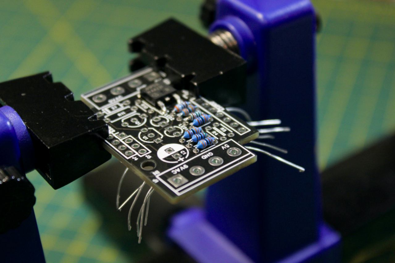
Next, I place all the components in this 'row' as they don't interfere with each other underneath. You can install the components in any order, I've just found this to be the easiest approach.
Splay the leads out sideways, but be careful as a few need to go 90° instead so they don't aim towards another solder point.
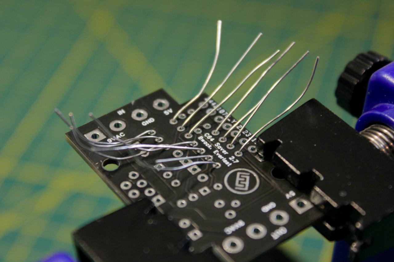
Once they're soldered in, trim them.
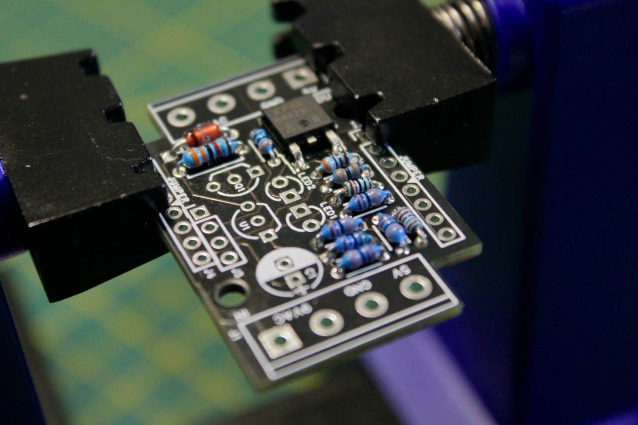
Repeat with the remaining resistors.
Take your time, and carefully add the remaining components.
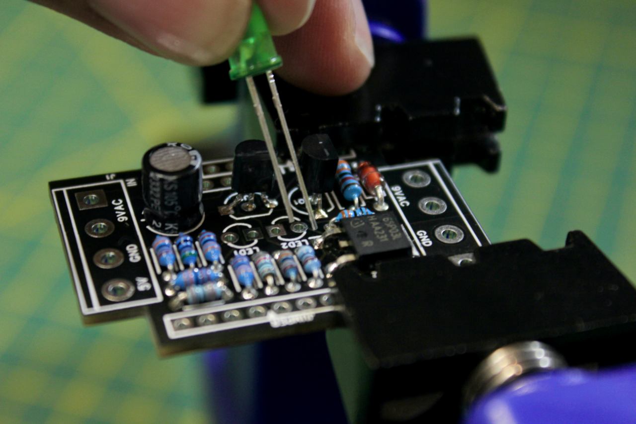
When you go to add the LEDs, notice that the longer lead on the LED goes into the round pad on the board. Also, the body of the LED usually has a flat "edge" which is marked on the PCB. The two flat edges on the LEDs face each other.
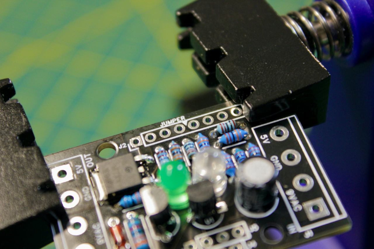
Finally, take some of your trimmed leads and use them to make a jumper in the two rows of empty holes. There are two small arrows with the word "JUMPER" in each row, so bend a lead in half and drop it into the holes on either side of the jumper. You can solder these from the top.

All your components are now installed and your board should look something like this!
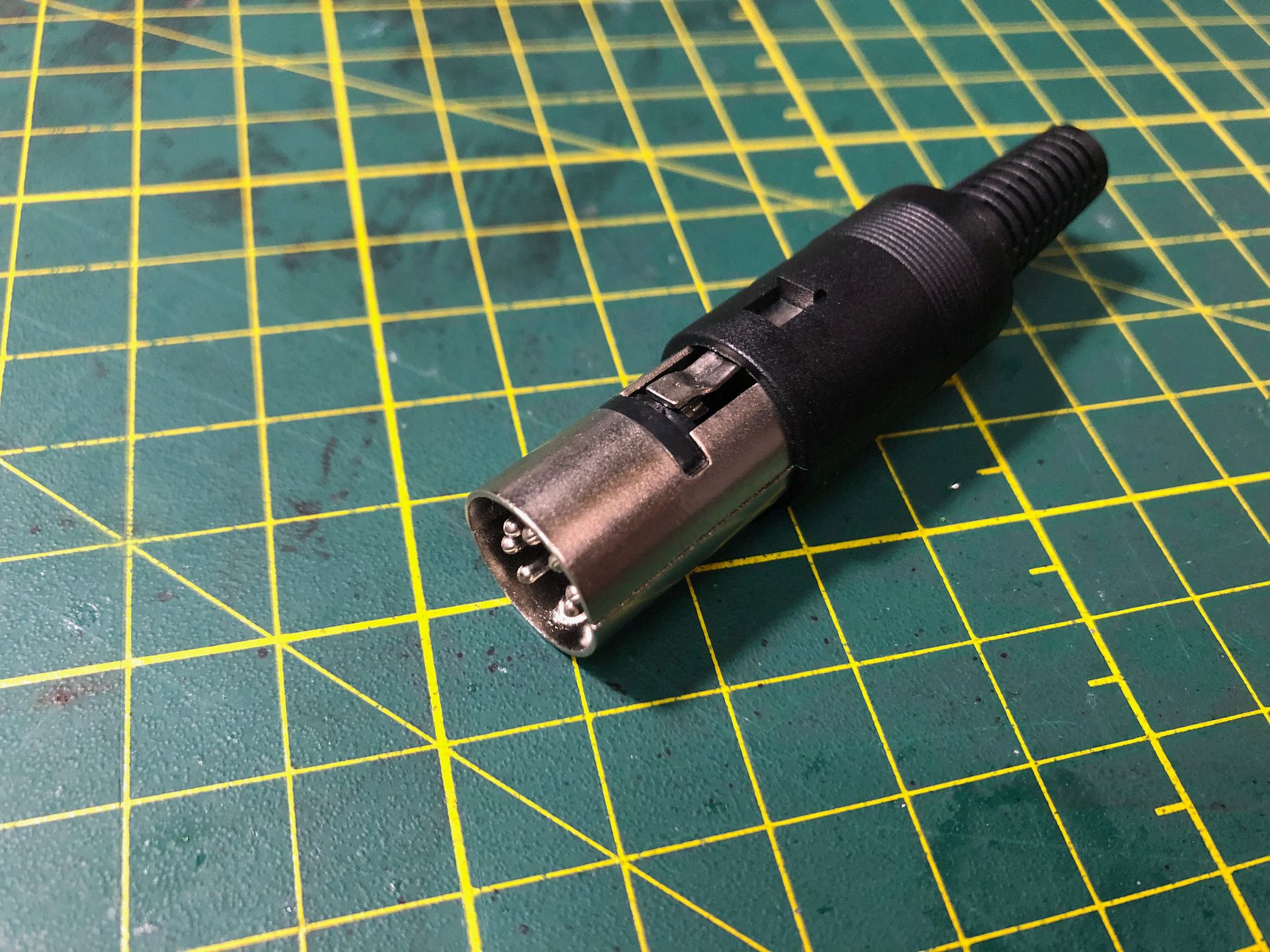
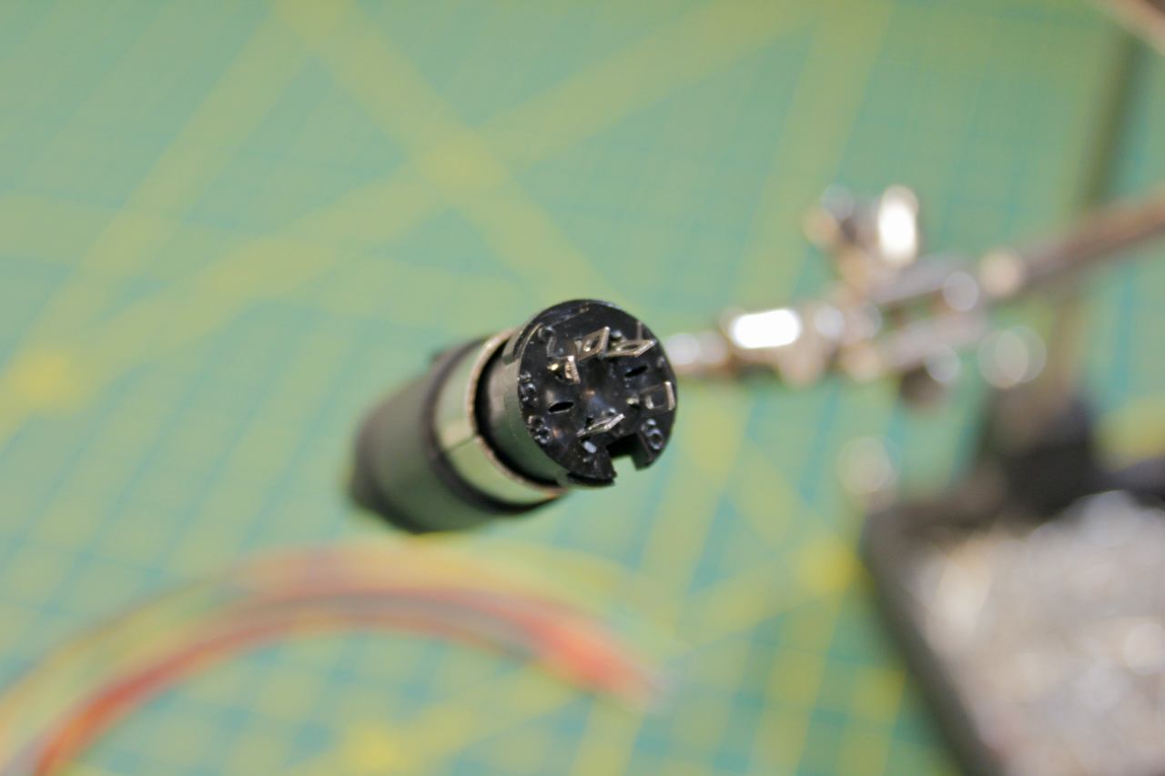
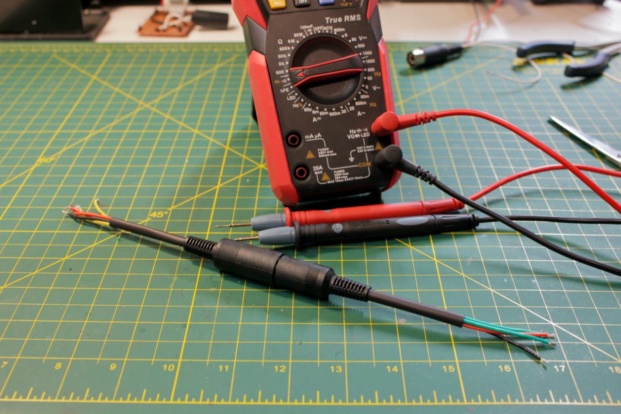
Next up, the DIN plugs! This is the end that goes into the Commodore. To get the sheath off, bent the little tab down into the center of the plug, then stick something inside from the 'wire end' to push the fitting out. It's tight!

Here you can see the pins where the wires get soldered. Notice the gap at the bottom where there is no pin. Use this to orient yourself when selecting the pins to solder, it's easy to get mixed up.
Notice that I'm using the other DIN connector to hold this one. This is because the heat from soldering will actually allow the plastic to move the pins slightly, causing them to be off-center or worse, loose. This works well to keep them in place.
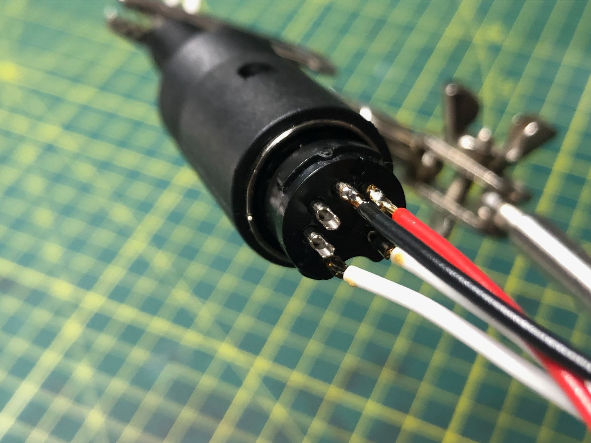
9VAC go to either side of the gap. Ground goes straight UP from the gap in the center pin, and 5V goes to the right of ground in this view. Ensure they can't touch by putting a little shrink wrap around the 5V pin. The rest are safe, but it doesn't hurt to put shrink wrap around each.
Bend the tab with the crimp area towards the center and put both metal fittings on before you crimp the wire in place. If you don't have the fittings in place when you crimp, the tension pulls the plug crooked.
Now let's move onto the input DIN.
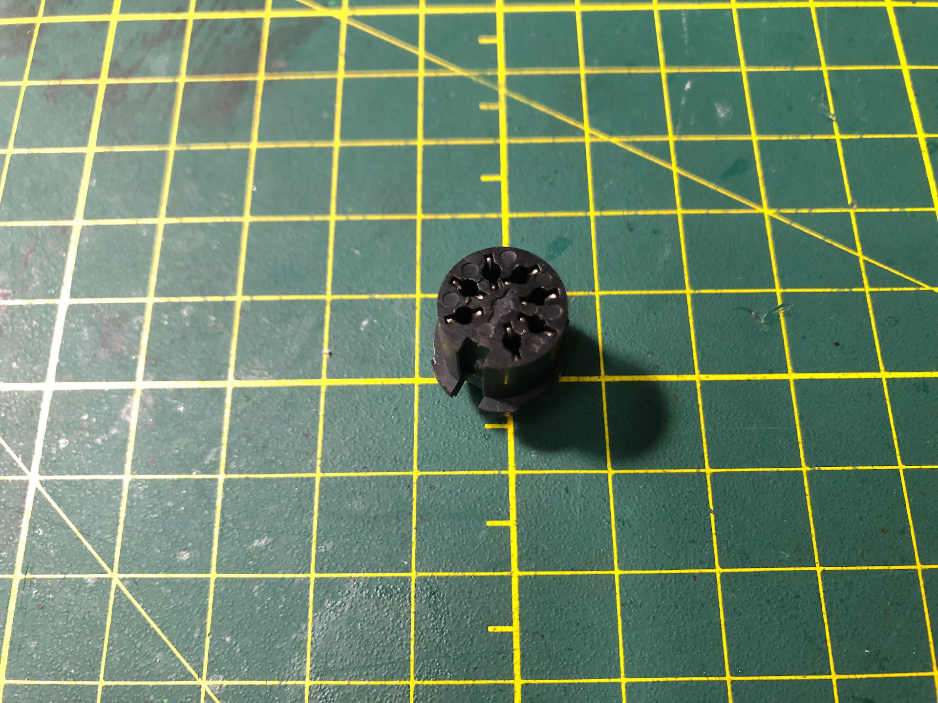
We don't need the two pins beside the 9VAC. So, take a set of small pliers and gently untwist the exposed end of the pin, and it will easily push out. I also bend the pins a little to make more room. You will notice that I have 5 pins here instead of four. Occasionally, a power supply will have power coming in on the wrong pin. To accommodate, the early units could take power on pins either side of the ground pin. Since I don't know where the power pin is, I run two wires from both and join them at the board. If you can determine which pin has power from your supply, you'd only need one wire and could remove the additional pin.
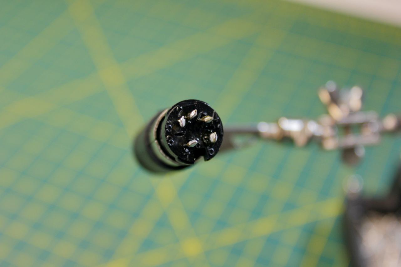
I've found the best way to solder this connector is to apply some flux to the pins and flow some solder onto each pin.
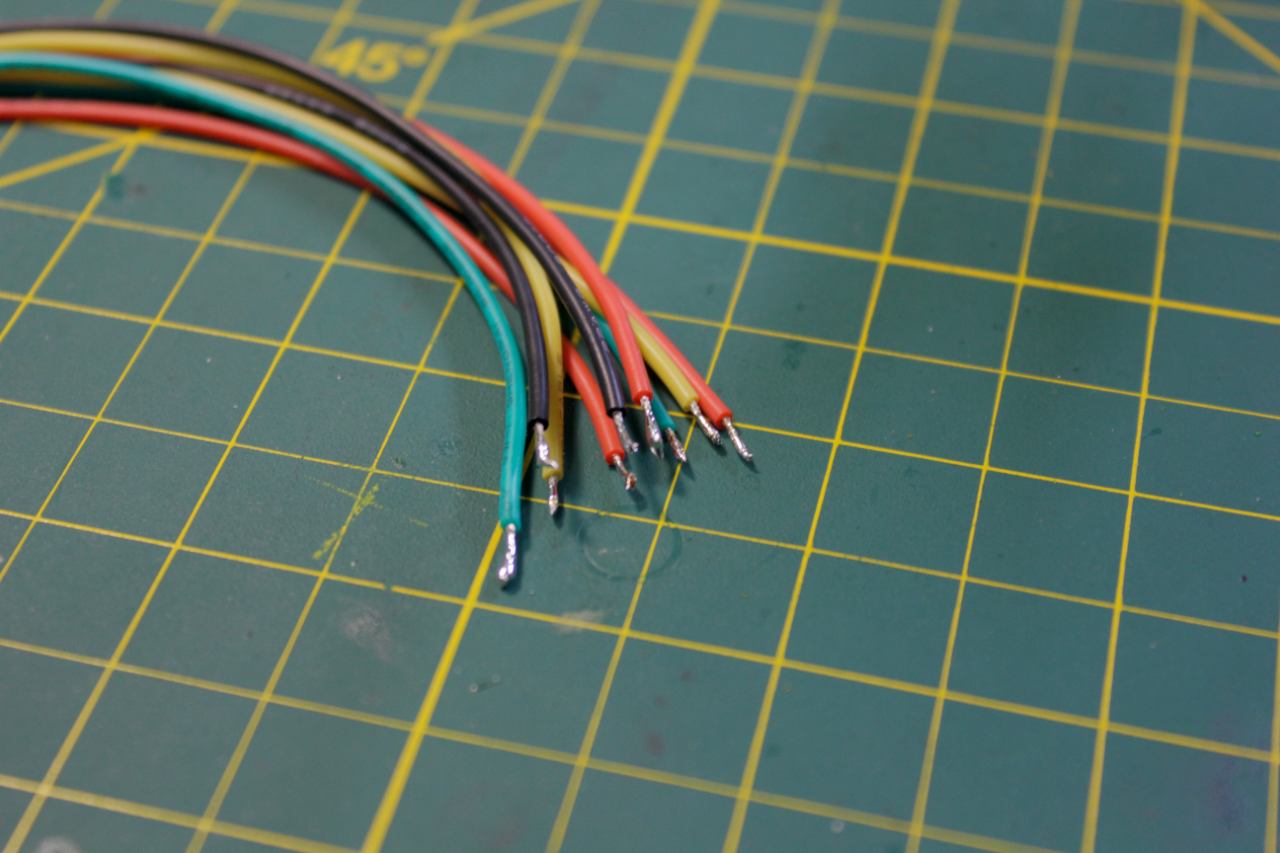
Then, tin the wires with flux and solder.
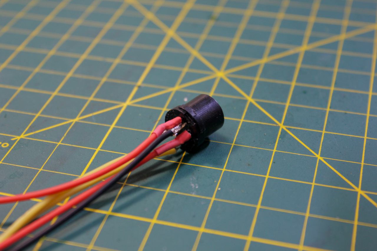
Finally, touch the solder iron to the pin and wire while they're touching and they'll form a secure connection. Again, put some shrink tube around the 5V connector(s).
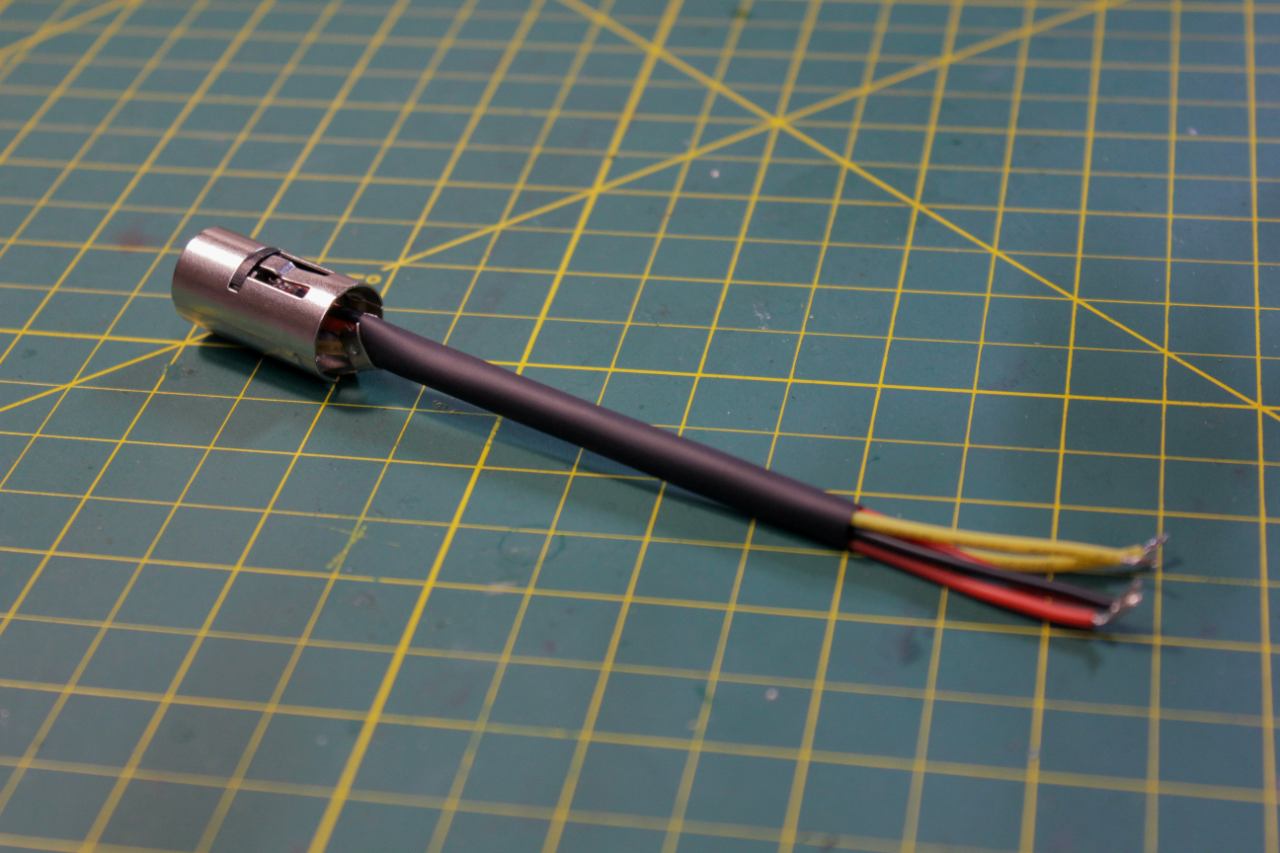
Here we see the fitting in place.
Once they're all done, connect them end to end and test with a meter for continuity.
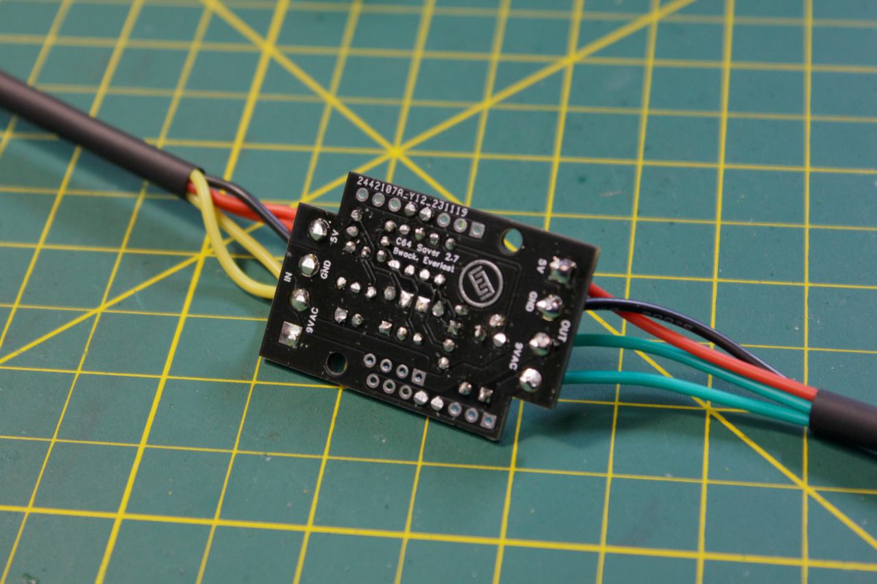
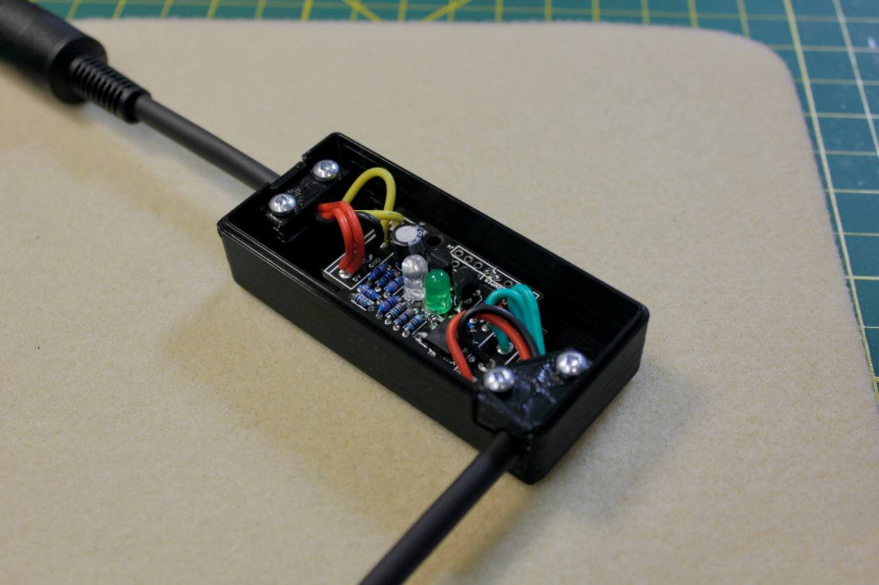
Connect up the harnesses to the board, paying CAREFUL attention to the IN text on the front of the board (seen in the next picture) which goes to the female plug. I usually solder the wires directly into the board. However, you may have the blue wire connector blocks that you can choose to use. I find there is more room to finesse the wires into the proper length by soldering directly to the board.
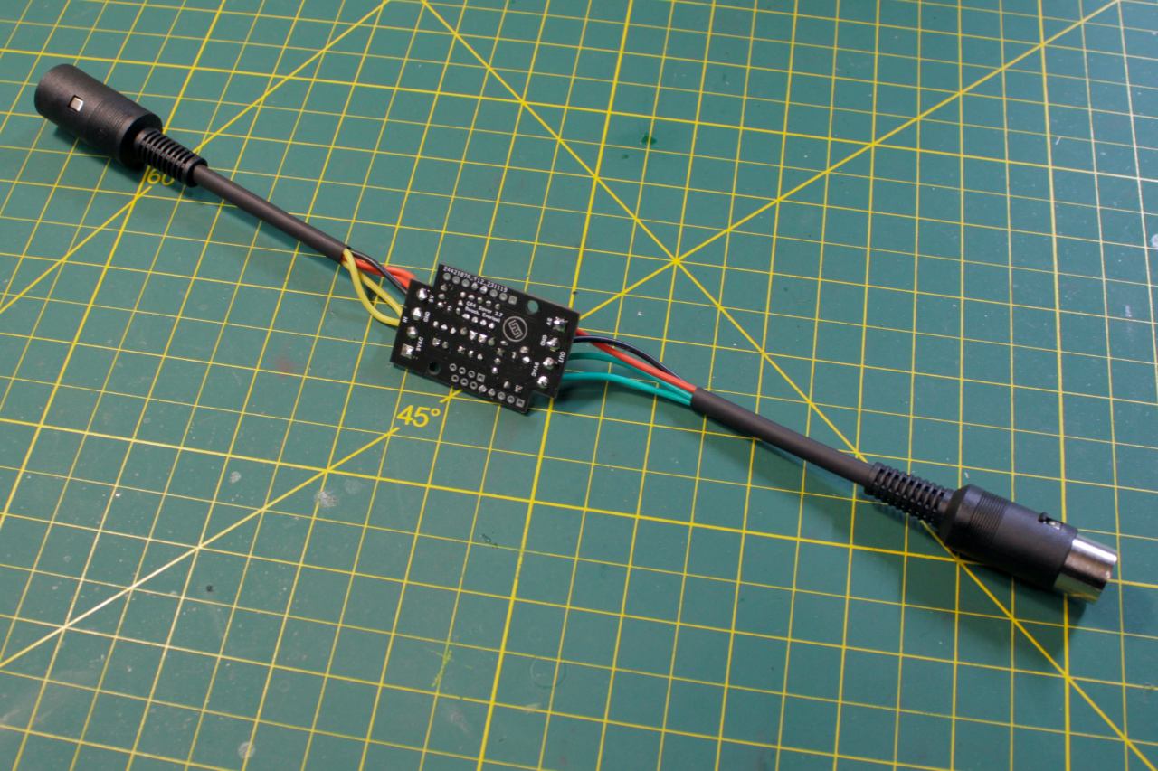
All done! Let's test it before installing it into the case.
Note the IN beside the 9VAC. That's the side that goes to the female DIN connector (and to the power supply).

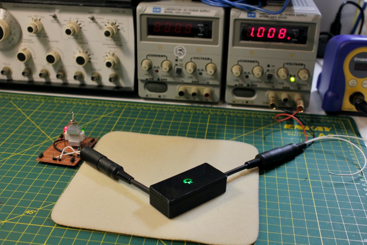
It's passing 5.3 volts through the unit just fine.
I'm using an adjustable bench power supply. If you don't have one, try plugging in your Commodore power supply for this step. Measure the voltage at the 5V in and 5V out. The 5V out could be up to 0.1V lower.
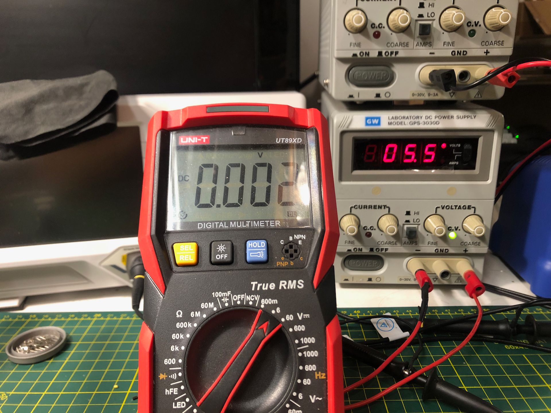
I bumped the voltage to 5.5V and now it's not allowing any voltage to pass through. Great! This particular unit cut off at 5.43V. Due to variations in the resistor values, I've seen values from 5.39V to 5.43V.
If you don't have an adjustable supply, feel free to put ANY voltage into the saver from 0 to 20V DC. It MUST be DC of course, but nothing in this range will hurt the Saver if not left for an extended period of time. I guess I should leave one at 20VDC for a while and see what happens!
Alright, let's install the saver in the case. You may have to take a craft knife to separate the 3d printed parts from the brim that supports it's while it's being made. Once you have all the pieces free of each other, starting putting them together!
This part is easy, just make sure the holes for the case are visible in the board. Note that I'm using Robertson screws. It's come to my attention that these are a Canadian Thing™ and nobody else seems to have them. They're by far the best kind of screw, and I can't imagine building a house with Philips. 🤮
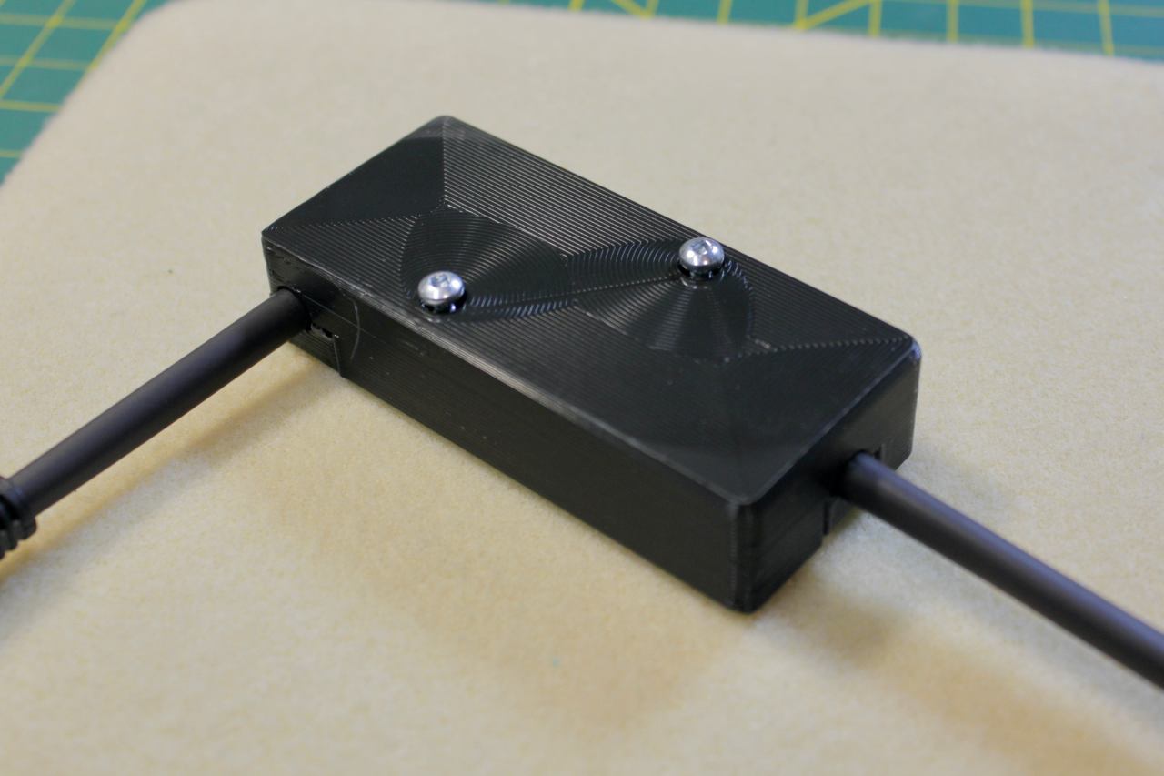
On the back, put in the longer screws most of the way in WITHOUT putting the top on. The tips of the screws will be at the surface of the board.
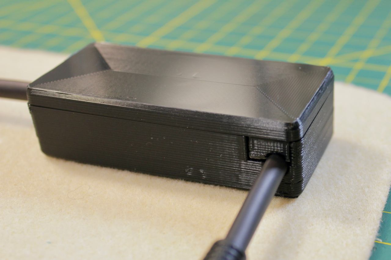
Put the lid on and screw it down carefully. Only tighten the screws enough to pull the two halves together cleanly.
When I ship these out, I test them carefully with a 1 amp load, and then test it on my own C64!
I hope you enjoyed my writeup on how to build a C64 Saver. Please favorite my Etsy store so you'll be notified of new products, and check out my Youtube channel and other links.
All the best, Jason